




Cracks, loose mounts, and uneven wear on ship anti-collision seals require different maintenance responses. A shallow surface crack does not carry the same risk as a tear through a mounting hole, and tightening a loose bolt will not correct a damaged backing structure. The immediate decision is whether the rubber profile can still absorb contact and transfer loads through its supports without detaching or exposing the vessel to direct impact.
The term “anti-collision seal” can describe several protective rubber profiles, including fender strips and hollow bumpers. These are not necessarily watertight seals. Inspection limits must therefore follow the installed profile’s function, mounting arrangement, and manufacturer’s instructions rather than a generic crack-size or wear threshold.
Make the contact area safe before judging the damage
Arrange inspection with the vessel secured and the protective profile unloaded. Keep personnel out of pinch points between the vessel and the quay, another vessel, or moving equipment. Where access requires work over water, at height, or from a small craft, use the applicable site controls. Do not reach behind a profile that can become compressed by vessel movement.
Remove salt deposits, mud, and marine growth using a cleaning method compatible with the rubber. Avoid unapproved solvents, aggressive wire brushing, and high-pressure cleaning that could enlarge cuts or damage bonded interfaces. A dirty surface can hide a crack, while a wet surface can make superficial marks difficult to distinguish from open splits.
Identify the profile type, rubber grade where documented, fastening method, and original dimensions. Previous inspection photographs are particularly useful: a defect’s growth can be more important than its appearance during one visit. Check whether the area recently experienced unusually hard contact, snagging, fuel exposure, or a change in berthing alignment.
Read cracks by their location and behavior
Map cracks along the contact face, corners, profile ends, bolt holes, and transitions between supported and unsupported sections. Record their length, visible opening, direction, and location against a fixed reference point. Do not force a blade or probe into a crack to estimate depth; this can extend the defect and produce an unreliable measurement.
Fine surface checking can reflect environmental aging, particularly where rubber remains under tensile strain. It still deserves monitoring, but it is different from a localized tear caused by impact or excessive movement. A narrow crack at rest may open significantly under service deformation, so appearance alone cannot establish remaining strength.
- Cracks around fasteners: Examine for elongated holes, washer impressions, and tearing toward the profile edge. These indicate a problem in the load-transfer area, not just surface deterioration.
- Splits at corners or profile transitions: Check for sharp supporting edges, excessive bending, or incorrect installation geometry that concentrates strain.
- Cracks across a hollow section: Assess whether the split interrupts the wall responsible for controlled compression. A small external opening may conceal more extensive internal damage.
- Separating layers or bonded interfaces: Treat visible separation as a distinct defect. Surface coating will not restore the original bond or structural continuity.
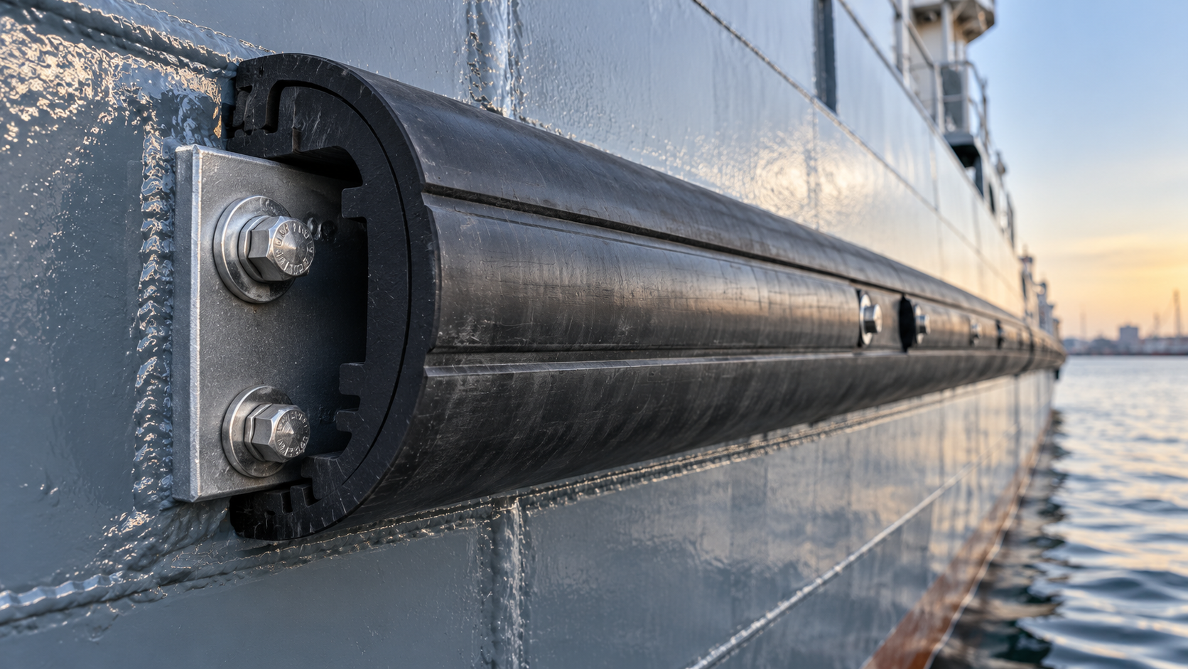
Any controlled deformation used to reveal crack opening should follow an approved inspection procedure. Do not improvise impact tests or load the profile with a vehicle, lever, or lifting appliance. If internal damage cannot be assessed visually, seek a manufacturer-approved examination method or remove the component for closer inspection.
Check the entire mounting system, not just bolt tightness
Loose mounts allow the rubber to shift before it begins absorbing contact as intended. This movement can concentrate loads on fewer fasteners, enlarge holes, and accelerate tearing. Look for displaced alignment marks, gaps behind the profile, polished contact marks, rust trails, missing hardware, and fretting around brackets or backing plates.
A loose nut is only one possible cause. Rubber compression set, damaged threads, corroded hardware, distorted brackets, and deterioration of the supporting structure can produce similar symptoms. On a metal support, inspect accessible coating breakdown, pitting, deformation, and suspect weld areas. On other substrates, check the relevant attachment and backing arrangement for cracking or movement.
Do not apply a generic torque value. Some designs use sleeves, stops, or backing plates to control clamping; others have different installation requirements. Excessive tightening can crush the rubber, pull a washer into it, or damage the attachment. Use the specified fastener grade, corrosion protection, locking method, tightening sequence, and torque or preload requirements.
If a fastener spins without tightening, repeatedly loosens, or sits in an elongated hole, investigate before returning the assembly to service. Replacing the nut alone does not restore a damaged anchor, torn rubber flange, or inadequate supporting plate. Where replacement hardware differs in material, confirm compatibility with the existing marine installation rather than assuming a corrosion-resistant bolt is automatically suitable.
Measure wear against the working profile
Wear matters because it changes both available clearance and the way the profile deforms. Compare the remaining section with the manufacturer’s drawing, an installation baseline, or an equivalent unworn area. Take measurements at repeatable locations and identify whether each value represents wall thickness, projection from the hull, or contact-face loss.
A rounded contact face can be acceptable only within the profile’s specified limits. A deeply flattened hollow bumper, a worn-through wall, or an exposed metal retainer represents a different condition. Visible rubber remaining on the hull does not prove that adequate impact protection remains.
Uneven wear provides evidence about the contact mechanism. Concentrated loss at one end can indicate angled contact or poor alignment. A narrow groove can point to a protruding quay fitting or rough opposing surface. Local tearing may indicate snagging rather than abrasion. Replacing the rubber without addressing the opposing surface or mounting position leaves the cause unchanged.
Also check for permanent flattening, unusual hardness, swelling, tackiness, or softening. These conditions can alter performance even when dimensional wear looks modest. Field hardness readings require a suitable instrument, sufficient material thickness, and a consistent method; readings on thin, curved, or unsupported surfaces should not be treated as conclusive evidence of material condition.
Separate monitoring from repair and withdrawal decisions
There is no universal allowable crack length, wear percentage, or bolt movement for ship anti-collision seals. Acceptance depends on geometry, compound, attachment design, contact energy, and the consequences of failure. Where manufacturer limits are unavailable, obtain a competent engineering assessment rather than creating numerical limits from visual appearance.
Adhesive filling, surface coating, and patching should not be assumed to restore impact capacity. Any repair must be approved for the compound, defect location, and loading arrangement. Temporary protection also needs an agreed operating restriction; it is not equivalent to a verified replacement.
Use replacement specifications to prevent repeat failures
A replacement should match more than the external outline. Confirm profile geometry, mounting-hole arrangement, compound requirements, dimensional tolerances, and relevant compression or energy-absorption performance. A similar-looking extrusion with different stiffness or wall geometry can transfer higher loads to the hull or compress too far during contact.
EPDM offers useful weathering and ozone resistance, but compound suitability depends on the actual exposure and mechanical demands. Petroleum oils and fuels require particular attention because EPDM is generally unsuitable for sustained contact with them. Reclaimed EPDM content alone does not establish whether a finished profile is suitable or unsuitable: formulation control and demonstrated finished-component performance are the relevant evidence.
Close the maintenance record with dated photographs, defect locations, measurements, mounting findings, corrective work, and a named release decision. Set the next inspection according to defect progression, contact frequency, operating exposure, and manufacturer guidance, with an additional check after abnormal impact. A repeatable record makes it possible to distinguish stable surface aging from a developing failure before the next contact tests the difference.
Leave A Message
If you are interested in our products and want to know more details, please leave a message here, we will reply you as soon as we can.