




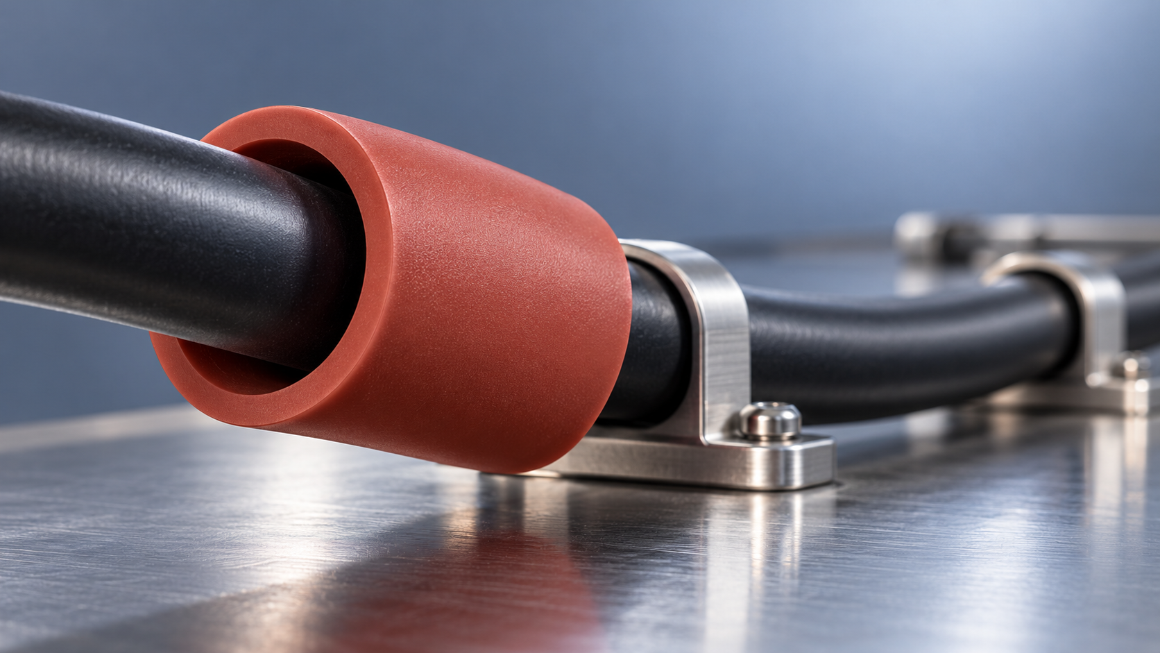
A silicone cable protector should be sized around the cable’s actual outside-diameter range, not its nominal diameter alone. Under heat and abrasion exposure, the right bore also depends on whether the protector must grip the cable, allow movement, or remain fixed while the cable flexes inside it. There is no universal clearance percentage that reliably covers all three conditions.
A tight fit can increase installation force and transfer friction into the cable jacket. Excessive clearance can allow migration, wrinkling, or repeated rubbing. The practical target is a controlled fit that remains functional across dimensional tolerances, operating temperatures, and the installed bend geometry—not simply the smallest bore that stretches over the cable.
Define where movement should occur
Before comparing bore sizes, establish the intended contact arrangement. A protector secured to a cable moves differently from a sleeve retained at a panel opening. Confusing these arrangements can produce a dimensionally correct part that wears at the wrong interface.
If retention is necessary, bore interference should not automatically replace a defined retention feature. A clamp, flange, or suitable end restraint can separate positioning from fit, although that feature must not crush the cable or create a new abrasion point.
Calculate the fit from tolerance limits
Obtain the cable manufacturer’s minimum and maximum outside diameters, including ovality where relevant. For a bundle, measure its installed envelope: ties, crossovers, and individual cable movement can make an equivalent circular diameter misleading. Connector bodies and splices also matter if a closed sleeve must pass over them during assembly.
For a round cable and bore, the basic dimensional checks are:
- Minimum diametral clearance = minimum protector bore − maximum cable outside diameter.
- Maximum diametral clearance = maximum protector bore − minimum cable outside diameter.
Positive values indicate clearance; negative values indicate nominal interference. Radial clearance is half the diametral value only for concentric, circular sections. In a horizontal installation, the cable can rest against one side despite having positive calculated clearance.
As an illustrative calculation, consider a cable specified at 10.0 ± 0.3 mm and a protector bore specified at 10.5 ± 0.2 mm. Minimum diametral clearance is zero, while maximum clearance is 1.0 mm. This is not a guaranteed free-running fit: the tightest permitted combination already reaches contact before bending, temperature effects, or local deformation are considered.
For an interference fit, a useful screening value is the required bore expansion:
Required bore expansion (%) = (cable diameter − relaxed bore diameter) ÷ relaxed bore diameter × 100.
This describes assembly geometry, not allowable continuous strain. Elongation at break is not a working fit limit. Contact pressure and installation force also depend on compound stiffness, wall geometry, surface condition, and engagement length.
Check the fit at temperature—not just the temperature rating
A material temperature rating does not establish that the assembled protector will retain its dimensions, grip, or abrasion resistance throughout service. Separate continuous exposure from short excursions, and distinguish ambient temperature from cable-jacket temperature. A nearby hot surface can also heat one side of the protector more strongly than the other.
For initial screening, free thermal expansion can be estimated using D(T) ≈ D₀[1 + αΔT], where α is the relevant linear thermal expansion coefficient. Use data applicable to the compound and temperature interval. A cable is a layered construction, so its outside-diameter response should not be inferred from the conductor’s expansion alone.
An unconstrained silicone sleeve expands with temperature, including its bore. However, the cable also changes dimension, and clamps, contact pressure, bends, and temperature gradients alter the installed response. It is therefore unsafe to assume either that heat always tightens the fit or that silicone expansion always creates sufficient clearance.
Temperature can change stiffness and frictional behavior; extended exposure can alter mechanical properties. Compression set matters where the design depends on sustained compression, while retained tear strength matters around stretched openings and cut ends. Relevant evidence is the compound’s performance after the specified exposure—not its initial hardness alone.
The protector can also change cable cooling. Adding a silicone layer or an enclosed air gap changes the heat-transfer path. Where current loading is significant, verify cable temperature in the protected assembly rather than assuming an unchanged electrical operating margin.
Abrasion exposure can change the material decision
Silicone’s flexibility and heat capability do not establish its suitability for severe sliding abrasion. Check whether the threat is vibration against a smooth support, repeated travel across an edge, rubbing inside the bore, or contact with abrasive particles. These mechanisms require different evidence.
A larger bore may reduce sustained squeeze on the cable, but it can also permit relative motion. A smaller bore may suppress motion while increasing contact pressure. Wear depends on both movement and contact loading, so neither direction is inherently safer.
Wall thickness adds material between the cable and the contact surface, but it is not a substitute for abrasion resistance. For a given outside diameter, increasing the bore reduces wall thickness. Increasing the outside diameter to preserve the wall can create interference with surrounding hardware or increase bending resistance.
Where sharp edges or sustained rubbing dominate, changing the contact geometry may be more effective than adjusting the bore. An edge radius, separate guide, or qualified abrasion-resistant outer layer can reduce the load imposed on the silicone. Any added reinforcement or coating requires its own assessment for flexibility, heat exposure, and cable-jacket compatibility.
Validate bends, installation, and combined exposure
A straight sample does not reproduce a constrained cable route. At a bend, the protector can flatten, wrinkle on the inside radius, or press the cable against its outer wall. The relevant clearance is the remaining passage at the tightest installed bend, not just the relaxed bore measured on the bench. The cable manufacturer’s minimum bend radius still applies.
Installation length also changes the result. A short ring that slides easily over a cable does not prove that a long sleeve will install without excessive force. Stretching a small bore over a connector may damage the protector even when its final fit around the cable appears acceptable. Split construction can avoid that assembly problem, but introduces seam-retention and exposure questions.
A useful qualification sequence reproduces the actual cable jacket, protector length, restraints, bend radius, and assembly method. It should examine:
- Assembly force, jacket marking, and damage at cut ends or seams.
- Fit and retention at the intended hot and cold conditions.
- Wear under representative contact load, motion, surface roughness, and contamination.
- Migration, tearing, and cable condition after thermal cycling and mechanical exposure.
Separate heat-aging and abrasion results help screen materials, but do not establish combined performance. If rubbing occurs while hot, test that condition. Define acceptance criteria before testing, including allowable migration, remaining protective wall, and cable-jacket damage.
The released specification should identify the silicone compound, bore and wall tolerances, measurement conditions, intended fit, and installed exposure limits. A slightly larger bore with controlled retention may outperform a stretched sleeve; a close fit may be appropriate where relative motion must be suppressed. The deciding evidence is whether the complete assembly maintains protection through its temperature and movement range—not whether the nominal dimensions look compatible.
Leave A Message
If you are interested in our products and want to know more details, please leave a message here, we will reply you as soon as we can.